Specifications
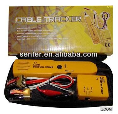
cable tracker used for RJ11 cable tracking and installation
This cable tracker is designed to identify and track cables or wires within a group without damaging the insulation. For telephone line, it can identify some states in the line. Owning this instrument, it is more convenient to install, debug and maintain telephone line. There is a sender and a receiver included in cable tracker.
Functions
Judge continuity of the cables or wires.
Track the cables or wires, and diagnose the break point.
Receive the tone signal on the cables or wires (telephone line)
Identify the state in the working telephone line (clear, ring, busy)
Send a signal solid tone or dual alternating tone to the object cables or wires.

Operation Instruction
1.Test continuity
1.Use the sender (switch to “CONT” )
Connect the test leads to the object pair, use “CONT” position. The bright green of “CONT” indicates the continuity (Line resistance not exceeding 10kΩ)
2.Use the Sender (Switch to “TONE” )
Connect the test leads to a pair of cables, touch receiver to cables. If the two cables give larger and same tones, it means both of them have continuity. Otherwise the cable which gives lower tone doesn’t have continuity
Connect one test lead to one cable among a group of cables, connect another cables to each ground. Touch the tip of receiver to another end of the cable mentioned above. Reception of tone means that cable has continuity.(see figure)
Note: Don’t connect to any active AC or DC circuit for measuring continuity.
2.Track cable or wires
Use sender (switch to tone) and receiver
Connect the test leads to the pair, or attach one test lead to ground and another test lead to either side of the line. Move the Receiver close to and along the pair (or the line). Reception of the tone indicates the track.
Note: Do not connect to any active circuit in this mode.
3. Identify the state of working telephone line
Use Sender (Switch to “off” )
1.Identify TIP&RING:
Connect the red test lead to the side of line and the black test lead to the side of another line.
“CONT” indicator light is “green” when you connect the red test lead to the RING (-) side.
“CONT” indicator light is “Red” when you connect the red test lead to the TIP (+) side.
2.Identify clear, ringing, busy state on the working telephone line:
Connect the red test lead to the RING side, black test lead to the TIP side, or connect RJ11 into the RJ11 socket on telephone.
“CONT” indicator light is green, indicates a CLEAR line. If “CONT” indicator light is “red” , it means the polarities were reversed.
“CONT” indicator does glow or glow faintly, indicates a BUSY line.
“CONT” indicator light brightly flickering “YELLOW” indicates a RINGING line. (Switch to “CONT” will terminate the call on the line.)